Devin Reade |
|
GNO Consortium | Home | GNO/ME |
This is a description of how to connect specific pieces of equipment to the Xyplex terminal server. While it's not specific to Xyplex servers, related serial communications information, especially with reference to Sun hardware, can be found at https://www.sunhelp.org, and in particular their UNIX Serial Port Resources page.
If you have additional related information, or know of errors or omissions in the following information, please contact me at the address at the bottom of this page.
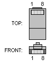
The sections below refer to rollover cables. These are serial cables with an RJ-45 plug at either end. They get their name because the flat cable normally used is effectively rolled over when making the connection:
	RJ-45			RJ-45
	1	RTS*	CTS*	8
	2	DTR	DSR	7
	3	TX	RX	6
	4	GND	GND	5
	5	GND	GND	4
	6	RX	TX	3
	7	DSR	DTR	2
	8	CTS*	RTS*	1
The astute reader will notice that a rollover cable is electrically equivalent to a null modem cable (as the pins are used by Cisco equipment).
Similarily, a straight-through cable is, well, straight through:
	RJ-45			RJ-45
	1	RTS*		1
	2	DTR		2
	3	TX		3
	4	GND		4
	5	GND		5
	6	RX		6
	7	DSR		7
	8	CTS*		8
(*) Whether pin 1 and 8 are RTS or CTS depends on the equipment in use (Cisco is shown). When constructing a straight through or roll-over cable, though, the actual name doesn't matter.
RJ-45 male connector:

	RJ-45				DB-25 male
	1	blue		CTS	RTS	4
	2	orange		DTR	DTR	20
	3	black		TX	TX	2
	4	red		TX-GND	GND	7
	5	green		RX-GND	GND	1
	6	yellow		RX	RX	3
	7	brown		DSR	DCD	8
	8	white or grey	RTS	CTS	5
The connection sequence is then:
Sun port A <--> DB25/RJ45 adapter <--> rollover cable <--> Xyplex
The console port of SunFire servers is identical to earlier servers. On the other hand, starting with machines around late 2001, Sun started providing the DB-25 to RJ-45 adapters with the machines. However, these adapters do not follow the wiring diagram specified above; they effectively cross the cables with respect to the previous description. As a consequence one does not use a rollover cable in this case. Instead, a straight-through cable should be used. Otherwise, the setup is identical as that described for older servers.
It should be noted that the Sun Enterprise 220R, the SunFire 280R, and perhaps other later models come with the RSC (Remote System Console) card. One piece of this card's functionality is in effect an on board terminal server. You may want to give it a try rather than using the Xyplex. Note that one cannot have console directed both to the serial A port and to the RSC card.
This information is based on the 2900XL switch. If you find differences with other switches, please let me know.
Cisco Catalyst switches have a female RJ-45 jack for the console port. To connect to the Xyplex RJ-45 jack, use a custom cable as described below. This one is kind of strange as Cisco and Xyplex define opposite rolls for pins 1 and 8 (RTS/CTS). The result is therefore similar to a rollover cable but without swapping the RTS/CTS pins. The DTR/DSR pins are also not used as they are not connected on the Cisco side, anyway:
	RJ-45			RJ-45
	1			1
	2			n/c
	3			6
	4			5
	5			4
	6			3
	7			n/c
	8			8
This information is based on the Cisco 2808. It may also apply to the Cisco 2100. Thanks to Andy Sparrow for this information.
The 2808 uses a male DB-9 connector for its serial port. Therefore a female DB-9 to RJ-45 cable is required:
	DB-9 Female		RJ-45
	1(6)	DCD		2
	2	RX		3
	3	TX		6
	4	DTR		7
	5	GND		5
	6(1)	DSR		2
	7	RTS		1
	8	CTS		8
In case it's not clear from the above, DSR and DCD are strapped together on the DB-9 end, and DSR goes to pin 2 (DTR) on the RJ-45.
This information is based on the 2500 series router. If you find differences with other routers, please let me know.
Based on pinout information on the 2500 series router console port, it appears that (unlike the Catalyst), the RTS/CTS lines are disconnected rather than the DSR/DTR lines. This means that the custom cable mentioned in the Catalyst section will still work at slow speeds, but will have absolutely no flow control.
Although they are completely untested, here are some other suggestions that you may wish to try if you are experiencing character loss:
If you have luck with any of the above methods, or find something else that works, please let me know.
In order to connect to traditional serial ports on x86 platforms, you either need to use a female DB-9 to female RJ-45 adapter, or a female DB-25 to female RJ-45 adapter, as appropriate for your machine.
The DB-9 adapter should be wired as follows. Note that colours may vary depending on the adapter's manufacturer:
	RJ-45				DB-9 female
	1	blue		RTS	7
	2	orange		DTR	4
	3	black		TX	3
	4	red		GND	5
	5	green		GND	n/c or short to other GND
	6	yellow		RX	2
	7	brown		DSR	6
	8	white or grey	CTS	8
The DB-25 adapter should be wired thus: (The following pinout has yet to be empirically verified as working.)
	RJ-45				DB-25 female
	1	blue		RTS	4
	2	orange		DTR	20
	3	black		TX	2
	4	red		GND	7
	5	green		GND	1
	6	yellow		RX	3
	7	brown		DSR	6
	8	white or grey	CTS	5
Note that there are at least two wiring "standards" used for the 10 pin dual inline connector that many systems use to connect to the motherboard. If you have problems, ensure that you have the right cables attached to your motherboard.
|
Contact me @ gdr at gno.org |
Last Updated: 26 Apr 2025 |
|